|
|
|
The IR-XX04 ULTIMATE LAser TAG GAME ENHANCEMENT PROP!
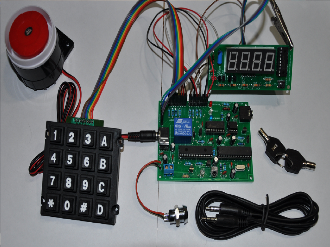
This set is a very unique and laser-tag specific game enhancement prop that talks to you! It has TONS of different functions that allow for you to customize your game play! Let me introduce to you to the IR-XX04 ULTIMATE game Enhancement prop! This unit is part of our laser-tag specific "LaserBlazer" series of laser tag props. Check out the rest of our LaserBlazer products on the front page of our website. The above video acts as a complete user manual, but there are also written instructions below. Make sure to watch the video! This set comes with a high quality numeric matrix keypad, with lots of holes for easy mounting, a loud siren, a stereo-stereo audio cable for interface with your own sound system, a main processor board, a countdown timer board, a key based power supply switch, several extra wires for wire-cut mode, a speaker (In case you do not wish to connect with your sound system), and a set of 2x keys! This unit was created to mimic our populate "Betty" products. It is a wonderful little prop that talks to you. It comes to you fully assembled and tested. There is a laser tag IR repeater function that becomes active if this unit is tampered with (Incorrect combination is entered/wrong wire is cut). This set is extremely easy to use, and ready to be mounted as soon as you receive it!
What if this unit doesn't work with my Laser Tag guns?
It should work and learn your gun signals with no issue as long as your laser tag guns are rated for 38kHz, and not 56kHz. If your laser tag guns are rated for 56kHz, simply send us a question. We can modify this unit to work with 56kHz laser tag guns.
This version has a default disarm code of Star (*), Number (#), 1, 1. You can also easily enter program mode during the power on sequence so that you can program in your own special code for that specific game. The only way to disarm this unit once it is running is to either cut/remove the correct disarm wire, or to enter in the correct combination. Entering an incorrect combination, shaking the assembled set, or cutting one of the incorrect wires will act to trigger a FAST countdown mode where the countdown timer counts down 10x times as fast. Just like in the movies!. If you cut the wrong wire, then cut the deactivation wire, it will have no effect. If you cut the incorrect wire, then the only way to disarm is to enter in the correct sequential 4-digit combination. If any of the three tamper modes are triggered (Incorrect Combo/Incorrect Wire Cut/Prop Vibration), then the countdown timer will immediately start counting down 10x times as fast. From there, the only way to disarm the system will be to enter in the correct combination.
The included loud siren is EXTREMELY LOUD! An 8-ohm 0.5 watt speaker is also included, so that the device can communicate with you. The countdown timer is easily programmed using only one button! You can program the game to be anywhere from 00:00 to 99:59 (1 hour/40 minutes). To top that off, there is a vibration tamper option that causes a FAST countdown if you are trying to be dishonest with the device! This vibration option can be easily disabled and re-enabled if you see fit. WATCH THE ABOVE VIDEO FOR A FULL DEMONSTRATION! On the countdown timer board, there is a little jumper labelled "VIB". If you remove this jumper, then the vibration tamper mode will be disabled.
This set also includes a whack of female-female wire connectors so that you have extra for wire-cut mode.
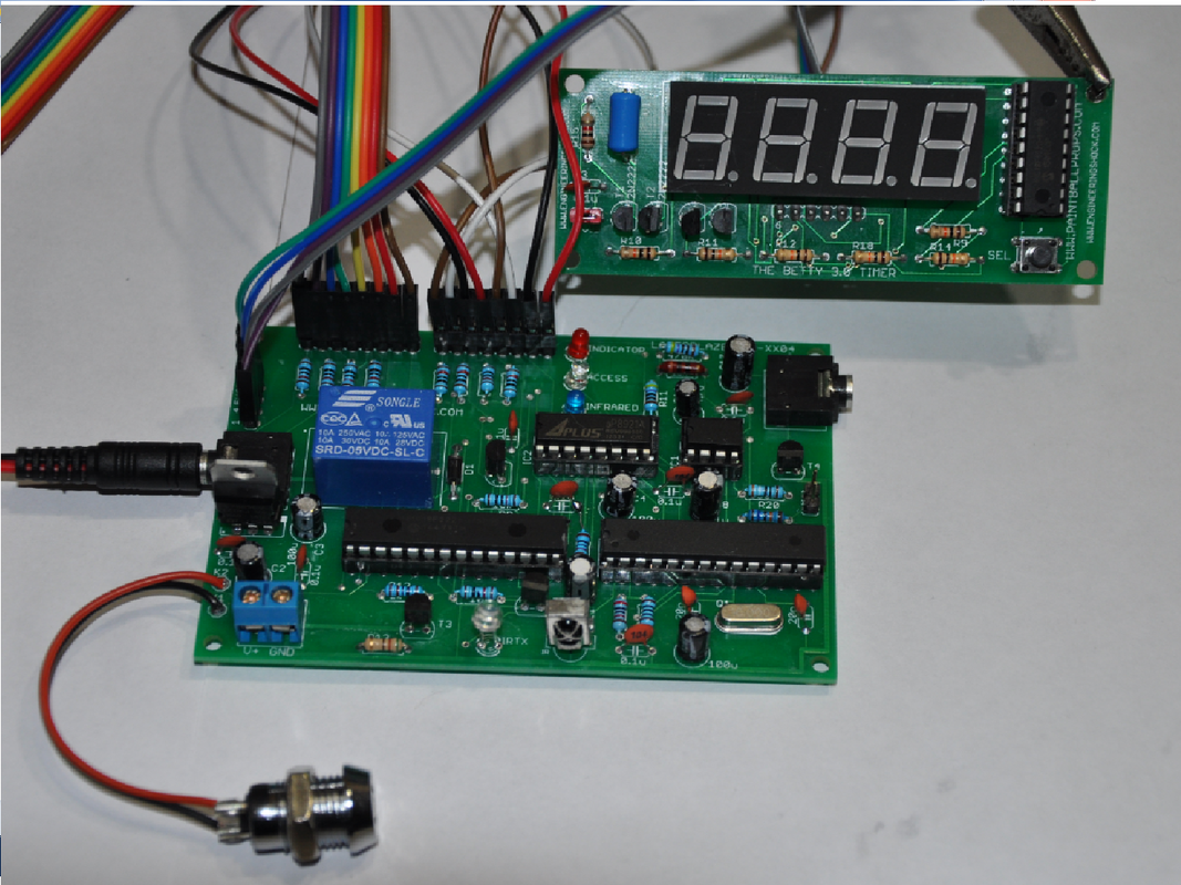
The video above may be long, but it gives you a full demonstration. It also shows you how each of the boards are connected together. The video above will serve as the primary manual for this product. I will speak about specifications and how it works below.
Some Preliminary Things To Note:
1) This device comes assembled, but without a casing. It is up to the user to mount both boards and the loud siren. Each component in this set is easily mountable. The loud siren also has mounting holes for easy installation. The loud siren also has a second mounting option. On the back-side of the siren, there is a two-sided tape strip. Simply remove the protective layer, and stick your siren to your project box.
2) A solid 9-12v power supply is required (Not included). If the voltage at the input drops below 7v, the device memory will not function correctly. The device will misbehave if the supply voltage falls below 7v. Your power source should be able to support 1A or higher. When in standby mode, this requires only a few milliamps to operate. When the siren goes off, it requires up to 700mA of current. Three to five 9v batteries in parallel (NOT SERIES) will work just fine. 5x 9v batteries in parallel will work even better. 5-6x D-Cell 1.5v batteries in series will work well too. Optimal is 11.1v LIPO or Lead Acid. Do not use dollar store batteries! Optimally, you'd want to have a rechargeable 9-12VDC battery pack with a current rating of 2000mAh or higher.
Disclaimer:
This prop module was created specifically to enhance your tactical gaming experience. Engineeringshock Electronics, paintballprops.com, and any affiliates of Engineeringshock Electronics will not be held accountable for losses or consequences caused by the misuse of this product, or any of our products. Furthermore, we will not offer servicing on products that have been modified in any way. By purchasing this product, you are agreeing to the above statement. Engineeringshock Electronics, paintballprops.com, and any affiliates of Engineeringshock Electronics prohibit the re-sale of this product, or any of our products. This product has been designed for the specific use of applications and may not be used for unlawful purposes, uses that are expressly prohibited under the terms, conditions and purpose of its use and diversion contrary to U.S. export laws. No guarantees are given or implied as to the product efficiency and performance. Company, its consultants, partners, agents and employees shall not be liable for any claims, losses, expenses, injuries, or damages arising from or related to the product
This Set Comes With:
1x Fully Assembled IR-XX04 ULTIMATE Laser-Tag game Enhancement Processor Board (Tested)
1x Fully Assembled Countdown Timer Board (Tested & Connected To The Main Processor Board)
1x Black 16-Digit Matrix Keypad (Tested & Connected To The Main Processor Board) - YOU CAN ALSO INQUIRE ABOUT A MEMBRANE KEYPAD! JUST ASK!
1x Loud Siren With Plug
1x 0.5W 8 Ohm Speaker (To be plugged into SPK header)
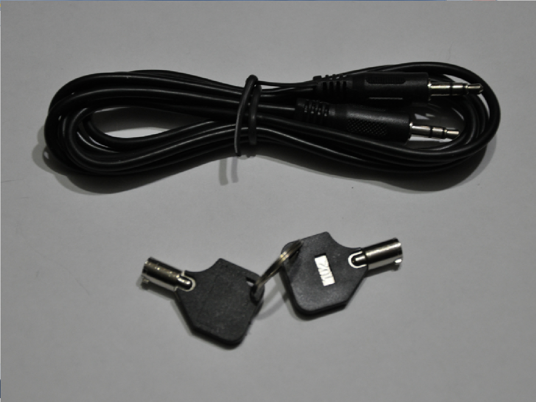
1x Stereo-Stereo Connector Cable
1x Power Key Module (Includes 2x keys)
1x Bundle Of Extra Wires For Wire-Cut Mode!
How It Works: (Watch the video for a full demonstration - Highly Recommended)
When you first receive your device and you have it mounted in your project box, power it up. The device will then communicate to you several different instructions. The default disarm code is Star, Number, 1, 1. If you do not have all of your wire-cut wires connected properly, then the red LED will light up during power up, and stay on until you do. The combination of Star, Number, 1, 1 will be the default code after every power up, unless you program in your own code. To program in your own special code for the game, power the device down and make sure that you are holding down the "1" button on the board while you re-apply power. Hold this button down until you hear "Enter Program Mode". Let go when you hear that. Then it will be able to enter in a four digit combination. Do so, and it will say "Code Programmed", "System Ready", "Program Wire"... If you don't want to program in a new code for the game, just power the device up as is. When you've entered in a new combination, the green "ACCESS" LED will flash, which indicates that your custom code will be used for that game. If you want to always be programming your own codes for each game, you'll have to make sure that when you power the device on, you are holding down the "1" button. Programmed disarm codes can only be used for one game at a time, and are deleted on power up.
Program Wire Mode:
When the device prompts the user to "Program Wire", it means that you get to choose which wire will be the deactivation wire. This is fun! If you look at the main board, there are four flying wire sets. Each wire is connected to two pins on an 8-pin header. Of the left hand side, look at the board. You will see that the left most pins are labelled "W1/W2/W3/W4", and that the right pins are simply labelled "COMMON". Each "W" must be connected to any of the pins on the COMMON rail. So W1 must always be connected to the common rail, W2 must be connected to the common rail, etc. When you are prompted to "Program Wire", the green LED will light up. At this point, you can press buttons 1, 2, 3, or 4 on the matrix keypad. Of course, by pressing button#1, you are selecting wire#1 to be your disarm wire. By pressing button#4, you are selecting wire#4 to be your disarm wire. IT IS THAT EASY! If you wish to wave this function, you can press the "Star" button on the matrix keypad when the unit prompts to "Program Wire". This will cut out the wire-cut function for the game, which means that cutting or pulling any wire for this game will do nothing.
Program Laser:
When the device prompts you to "Program Laser", it means that it is time to use any laser tag gun from your team to shoot the IR receiver on the board. as long as your laser tag gun is rated for 38kHz, then as soon as you've shot the sensor, the blue LED should blink, which means that your specific laser tag gun signal has been programmed successfully. If during gameplay the unit is tampered with via entering in an incorrect combination or cutting the wrong deactivation wire, then this signal will be repeated and shot back through the IR transmitter, which will damage on-coming players from the opposite team. When this happens, the blue LED will light up and blink every five seconds or so. It will transmit the signal once every time this blue LED turns on. If the device is not tampered with, then this function will lay dormant. If you wish to wave this function, you can press the "Star" button on the matrix keypad when the unit prompts to "Program laser". This will cut out the laser repeater function for the game.
Ready Clock:
When you apply power to this prop, power should also be reaching the countdown timer board. This device can be programmed up to 99 minutes and 59 seconds (9956), so there is a limitation relative to time. Upon power up, the right most digit will show a "0". This is the "Second" digit, and it can be programmed up to a value of "9" by tapping the SELbutton on the countdown timer board. You should only start programming in your game time once the unit gives you the "Ready Clock" instruction. If the user increments this digit past a value of 9, the digit will reset back to 0. Once you are done programming the "Second" digit, hold the S1 button down for a few seconds, then let go, and the next digit to the left lights up. This is the "10-second" digit, and it can be programmed up to a maximum value of 5. The right most digit and this digit work to program the seconds of the counter up to a maximum value of "59". Once you're done programming the 10-second digit, hold the SEL button down for a few seconds, then let go. The digit that is second from the left will light up. This is your "minute" digit, and it can be programmed up to a maximum value of 9. Once you are done programming this digit, hold the SEL button down again for a few seconds, and then let go. The left-most digit lights up, and this is your "10-minute digit". You can program this up to a value of 9. Once you've programmed in this digit value, press and hold the "1" button one more time, then let go. No digits should be lit up. From here, one quick tap on the 1 button will start the countdown. ONCE YOU HAVE DONE THIS, PRESS THE "1" BUTTON ON THE KEYPAD MATRIX TO START THE GAME!
System Ready:
When the device says (System Ready), it will follow with (Enter Combination). From here, the correct combination or the correct wire being cut-removed will deactivate the system. The default code is Star, Number, 1, 1. That will be the default code after every power up, unless you program in your own code. If the clock runs out, the alarm will sound. If you enter in the wrong combination, the system will tell the countdown timer to start counting down 20x times as fast. The main Proessor board will say "Incorrect Combination", then "Enter Combination". If you deactivate the system, the device will say "System Deactivated", then the device will reset.
On Board Vibration Sensor - Overall Tamper:
There are three methods of tampering with this device:
1) An incorrect combination is entered.
2) The incorrect wire is cut.
3) The user is violent, or running with the prop.
The countdown timer board has a vibration sensor on it that can be enabled or disabled by following the steps in the above video. Please note this when you are using the board.
WHEN THE ALARM GOES OFF...
When the alarm is activated after the timer runs out,the user WILL NOT be able to turn it off until after the red LED is turned off. When the alarm is triggered, the user has to wait a minimum of 5 seconds until th1 red LED turns off before the alarm can be deactivated. After the red LED turns off, the user can press the "1" button on the keypad to disable the siren and reset the system.
Power Requirements:
Power is connected through the two pin power terminal block. The pin labelled V+ (On board) is where you connect your positive DC voltage (9-12VDC). The GND terminal is the DC ground terminal for your DC ground line (Negative).
I have tried to outline what power is consumed at certain points below at different supply voltages so that you can better determine if your power source will do. The currents are rough, but should be accurate to 10%. It is hard to nail it down because the digits on the clock will weigh on the current consumption at any given time. At 12v input, the siren is louder, but it consumes more current. At 9v, the device consumes less current on the whole, but the siren is less loud. However, it is still certainly loud enough to wake the dead! Please note that the on board regulator will get HOT when the input supply is 12v, but it will not be damaged. Just be careful not to touch it. Also, if you have 11v-12v powering the board, try to make sure that if the alarm is triggered that you keep the siren on for no longer than 30 seconds. This is not an issue if the device is being powered at 9v-10v.
Input Supply Voltage: 8.0v Min to 12v MAX - Nominal is 9v.
Full System Current Consumption At 12v:
Standby Current: 25mA (Depending On Clock)
Relay Activated (No Siren): 80mA
Siren Activated: Pulsing 400mA- 700mA
Full System Current Consumption At 9v:
Standby Current: 15mA - 20mA
Relay Activated (No Siren): 40mA
Siren Activated: Pulsing 350mA- 700mA
Main Board Size Specifications:
Length: 100mm
Width: 78mm
Height: 18mm
Countdown Timer Board Size Specifications:
Length: 90mm
Width: 36mm
Height: 11mm
Siren Size Specifications:
Base Length: 64mm
Base Width: 54mm
Height: 49mm
Matrix Keypad Specifications:
Base Length: 81mm
Base Width: 75mm
Height: 19mm
Key Module Mounting Diameter = 11.5mm
If you have any questions at all, please do not hesitate to ask! Please make sure to watch the video! Thanks for taking an interest!
What if this unit doesn't work with my Laser Tag guns?
It should work and learn your gun signals with no issue as long as your laser tag guns are rated for 38kHz, and not 56kHz. If your laser tag guns are rated for 56kHz, simply send us a question. We can modify this unit to work with 56kHz laser tag guns.
This version has a default disarm code of Star (*), Number (#), 1, 1. You can also easily enter program mode during the power on sequence so that you can program in your own special code for that specific game. The only way to disarm this unit once it is running is to either cut/remove the correct disarm wire, or to enter in the correct combination. Entering an incorrect combination, shaking the assembled set, or cutting one of the incorrect wires will act to trigger a FAST countdown mode where the countdown timer counts down 10x times as fast. Just like in the movies!. If you cut the wrong wire, then cut the deactivation wire, it will have no effect. If you cut the incorrect wire, then the only way to disarm is to enter in the correct sequential 4-digit combination. If any of the three tamper modes are triggered (Incorrect Combo/Incorrect Wire Cut/Prop Vibration), then the countdown timer will immediately start counting down 10x times as fast. From there, the only way to disarm the system will be to enter in the correct combination.
The included loud siren is EXTREMELY LOUD! An 8-ohm 0.5 watt speaker is also included, so that the device can communicate with you. The countdown timer is easily programmed using only one button! You can program the game to be anywhere from 00:00 to 99:59 (1 hour/40 minutes). To top that off, there is a vibration tamper option that causes a FAST countdown if you are trying to be dishonest with the device! This vibration option can be easily disabled and re-enabled if you see fit. WATCH THE ABOVE VIDEO FOR A FULL DEMONSTRATION! On the countdown timer board, there is a little jumper labelled "VIB". If you remove this jumper, then the vibration tamper mode will be disabled.
This set also includes a whack of female-female wire connectors so that you have extra for wire-cut mode.
The video above may be long, but it gives you a full demonstration. It also shows you how each of the boards are connected together. The video above will serve as the primary manual for this product. I will speak about specifications and how it works below.
Some Preliminary Things To Note:
1) This device comes assembled, but without a casing. It is up to the user to mount both boards and the loud siren. Each component in this set is easily mountable. The loud siren also has mounting holes for easy installation. The loud siren also has a second mounting option. On the back-side of the siren, there is a two-sided tape strip. Simply remove the protective layer, and stick your siren to your project box.
2) A solid 9-12v power supply is required (Not included). If the voltage at the input drops below 7v, the device memory will not function correctly. The device will misbehave if the supply voltage falls below 7v. Your power source should be able to support 1A or higher. When in standby mode, this requires only a few milliamps to operate. When the siren goes off, it requires up to 700mA of current. Three to five 9v batteries in parallel (NOT SERIES) will work just fine. 5x 9v batteries in parallel will work even better. 5-6x D-Cell 1.5v batteries in series will work well too. Optimal is 11.1v LIPO or Lead Acid. Do not use dollar store batteries! Optimally, you'd want to have a rechargeable 9-12VDC battery pack with a current rating of 2000mAh or higher.
Disclaimer:
This prop module was created specifically to enhance your tactical gaming experience. Engineeringshock Electronics, paintballprops.com, and any affiliates of Engineeringshock Electronics will not be held accountable for losses or consequences caused by the misuse of this product, or any of our products. Furthermore, we will not offer servicing on products that have been modified in any way. By purchasing this product, you are agreeing to the above statement. Engineeringshock Electronics, paintballprops.com, and any affiliates of Engineeringshock Electronics prohibit the re-sale of this product, or any of our products. This product has been designed for the specific use of applications and may not be used for unlawful purposes, uses that are expressly prohibited under the terms, conditions and purpose of its use and diversion contrary to U.S. export laws. No guarantees are given or implied as to the product efficiency and performance. Company, its consultants, partners, agents and employees shall not be liable for any claims, losses, expenses, injuries, or damages arising from or related to the product
This Set Comes With:
1x Fully Assembled IR-XX04 ULTIMATE Laser-Tag game Enhancement Processor Board (Tested)
1x Fully Assembled Countdown Timer Board (Tested & Connected To The Main Processor Board)
1x Black 16-Digit Matrix Keypad (Tested & Connected To The Main Processor Board) - YOU CAN ALSO INQUIRE ABOUT A MEMBRANE KEYPAD! JUST ASK!
1x Loud Siren With Plug
1x 0.5W 8 Ohm Speaker (To be plugged into SPK header)
1x Stereo-Stereo Connector Cable
1x Power Key Module (Includes 2x keys)
1x Bundle Of Extra Wires For Wire-Cut Mode!
How It Works: (Watch the video for a full demonstration - Highly Recommended)
When you first receive your device and you have it mounted in your project box, power it up. The device will then communicate to you several different instructions. The default disarm code is Star, Number, 1, 1. If you do not have all of your wire-cut wires connected properly, then the red LED will light up during power up, and stay on until you do. The combination of Star, Number, 1, 1 will be the default code after every power up, unless you program in your own code. To program in your own special code for the game, power the device down and make sure that you are holding down the "1" button on the board while you re-apply power. Hold this button down until you hear "Enter Program Mode". Let go when you hear that. Then it will be able to enter in a four digit combination. Do so, and it will say "Code Programmed", "System Ready", "Program Wire"... If you don't want to program in a new code for the game, just power the device up as is. When you've entered in a new combination, the green "ACCESS" LED will flash, which indicates that your custom code will be used for that game. If you want to always be programming your own codes for each game, you'll have to make sure that when you power the device on, you are holding down the "1" button. Programmed disarm codes can only be used for one game at a time, and are deleted on power up.
Program Wire Mode:
When the device prompts the user to "Program Wire", it means that you get to choose which wire will be the deactivation wire. This is fun! If you look at the main board, there are four flying wire sets. Each wire is connected to two pins on an 8-pin header. Of the left hand side, look at the board. You will see that the left most pins are labelled "W1/W2/W3/W4", and that the right pins are simply labelled "COMMON". Each "W" must be connected to any of the pins on the COMMON rail. So W1 must always be connected to the common rail, W2 must be connected to the common rail, etc. When you are prompted to "Program Wire", the green LED will light up. At this point, you can press buttons 1, 2, 3, or 4 on the matrix keypad. Of course, by pressing button#1, you are selecting wire#1 to be your disarm wire. By pressing button#4, you are selecting wire#4 to be your disarm wire. IT IS THAT EASY! If you wish to wave this function, you can press the "Star" button on the matrix keypad when the unit prompts to "Program Wire". This will cut out the wire-cut function for the game, which means that cutting or pulling any wire for this game will do nothing.
Program Laser:
When the device prompts you to "Program Laser", it means that it is time to use any laser tag gun from your team to shoot the IR receiver on the board. as long as your laser tag gun is rated for 38kHz, then as soon as you've shot the sensor, the blue LED should blink, which means that your specific laser tag gun signal has been programmed successfully. If during gameplay the unit is tampered with via entering in an incorrect combination or cutting the wrong deactivation wire, then this signal will be repeated and shot back through the IR transmitter, which will damage on-coming players from the opposite team. When this happens, the blue LED will light up and blink every five seconds or so. It will transmit the signal once every time this blue LED turns on. If the device is not tampered with, then this function will lay dormant. If you wish to wave this function, you can press the "Star" button on the matrix keypad when the unit prompts to "Program laser". This will cut out the laser repeater function for the game.
Ready Clock:
When you apply power to this prop, power should also be reaching the countdown timer board. This device can be programmed up to 99 minutes and 59 seconds (9956), so there is a limitation relative to time. Upon power up, the right most digit will show a "0". This is the "Second" digit, and it can be programmed up to a value of "9" by tapping the SELbutton on the countdown timer board. You should only start programming in your game time once the unit gives you the "Ready Clock" instruction. If the user increments this digit past a value of 9, the digit will reset back to 0. Once you are done programming the "Second" digit, hold the S1 button down for a few seconds, then let go, and the next digit to the left lights up. This is the "10-second" digit, and it can be programmed up to a maximum value of 5. The right most digit and this digit work to program the seconds of the counter up to a maximum value of "59". Once you're done programming the 10-second digit, hold the SEL button down for a few seconds, then let go. The digit that is second from the left will light up. This is your "minute" digit, and it can be programmed up to a maximum value of 9. Once you are done programming this digit, hold the SEL button down again for a few seconds, and then let go. The left-most digit lights up, and this is your "10-minute digit". You can program this up to a value of 9. Once you've programmed in this digit value, press and hold the "1" button one more time, then let go. No digits should be lit up. From here, one quick tap on the 1 button will start the countdown. ONCE YOU HAVE DONE THIS, PRESS THE "1" BUTTON ON THE KEYPAD MATRIX TO START THE GAME!
System Ready:
When the device says (System Ready), it will follow with (Enter Combination). From here, the correct combination or the correct wire being cut-removed will deactivate the system. The default code is Star, Number, 1, 1. That will be the default code after every power up, unless you program in your own code. If the clock runs out, the alarm will sound. If you enter in the wrong combination, the system will tell the countdown timer to start counting down 20x times as fast. The main Proessor board will say "Incorrect Combination", then "Enter Combination". If you deactivate the system, the device will say "System Deactivated", then the device will reset.
On Board Vibration Sensor - Overall Tamper:
There are three methods of tampering with this device:
1) An incorrect combination is entered.
2) The incorrect wire is cut.
3) The user is violent, or running with the prop.
The countdown timer board has a vibration sensor on it that can be enabled or disabled by following the steps in the above video. Please note this when you are using the board.
WHEN THE ALARM GOES OFF...
When the alarm is activated after the timer runs out,the user WILL NOT be able to turn it off until after the red LED is turned off. When the alarm is triggered, the user has to wait a minimum of 5 seconds until th1 red LED turns off before the alarm can be deactivated. After the red LED turns off, the user can press the "1" button on the keypad to disable the siren and reset the system.
Power Requirements:
Power is connected through the two pin power terminal block. The pin labelled V+ (On board) is where you connect your positive DC voltage (9-12VDC). The GND terminal is the DC ground terminal for your DC ground line (Negative).
I have tried to outline what power is consumed at certain points below at different supply voltages so that you can better determine if your power source will do. The currents are rough, but should be accurate to 10%. It is hard to nail it down because the digits on the clock will weigh on the current consumption at any given time. At 12v input, the siren is louder, but it consumes more current. At 9v, the device consumes less current on the whole, but the siren is less loud. However, it is still certainly loud enough to wake the dead! Please note that the on board regulator will get HOT when the input supply is 12v, but it will not be damaged. Just be careful not to touch it. Also, if you have 11v-12v powering the board, try to make sure that if the alarm is triggered that you keep the siren on for no longer than 30 seconds. This is not an issue if the device is being powered at 9v-10v.
Input Supply Voltage: 8.0v Min to 12v MAX - Nominal is 9v.
Full System Current Consumption At 12v:
Standby Current: 25mA (Depending On Clock)
Relay Activated (No Siren): 80mA
Siren Activated: Pulsing 400mA- 700mA
Full System Current Consumption At 9v:
Standby Current: 15mA - 20mA
Relay Activated (No Siren): 40mA
Siren Activated: Pulsing 350mA- 700mA
Main Board Size Specifications:
Length: 100mm
Width: 78mm
Height: 18mm
Countdown Timer Board Size Specifications:
Length: 90mm
Width: 36mm
Height: 11mm
Siren Size Specifications:
Base Length: 64mm
Base Width: 54mm
Height: 49mm
Matrix Keypad Specifications:
Base Length: 81mm
Base Width: 75mm
Height: 19mm
Key Module Mounting Diameter = 11.5mm
If you have any questions at all, please do not hesitate to ask! Please make sure to watch the video! Thanks for taking an interest!
|
|
|